In this article I shall discuss the architecture for logical routing in NSX-T, from the perspective of east/west routing. Read on, or click on the link in your Alexa app.
Ok so firstly let’s recap logical routing in NSX-V. In NSX-V there were two main routing components, the Distributed Logical Router (DLR) and the Edge Services Gateway (ESG). The DLR handled east/west traffic, and the ESG handled routing for north/south traffic, as well as stateful services if required. In addition, if you enabled dynamic routing you would deploy the Control-VM, which support the control plane functionality for the DLR. Sound familiar …. ok now forget it. The only thing that really resembles anything similar is that we have a distributed routing function in NSX-T, and we have a routing function that provides stateful services, that sites on an object called an Edge node. BUT neither of these are exactly like the DLR and/or the ESG. So any assumptions you’ve made, park them.
Now that’s out of the way ….
In NSX-T we have the concept of a Logical Router, and that is it. Yet this Logical Router (LR) can perform both a distributed or centralised functions. Which is where the similarity, with the DLR/ESG, begins and ends. In NSX-T you have the option to deploy your LR as either a Tier-0 or a Tier-1 router, and it’s important to understand the differences.
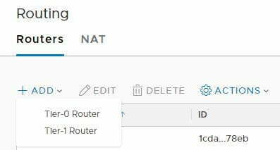
Diagram 1: Options to add a router
- Tier-0: Supports uplink capability to your physical infrastructure, supports connectivity to logical switches (single-tier topology), as well as being used as an interconnect with Tier-1 LRs.
- Tier-1: Supports connectivity to logical switches and to Tier0 (multi-tier topology)
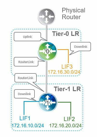
Diagram 2: T0/T1 Interconnectivity
For now, don’t worry about the topology piece, I’ll come back to that, but notice I don’t mention DLR or ESG, the only two router types you can deploy is a Tier-0 or Tier-1 router. Confused yet, bear with me and we’ll get there. OK, so by default when you deploy a Logical Router it’s deployed as a distributed routing instance. So irrespective of Tier-0 or Tier-1 you get a DLR like function. The LR, whether it’s a Tier-0 or Tier-1, is distributed across all your hypervisors.
So now let’s quickly circle back to the topology. You do not need to deploy Tier-1 LRs, or rather you do not need to deploy the two-tier topology depicted unless you need it. You would need it if you were a multi-tenanted environment, so you want the tenant Tier-1 LRs, and the Tier-0 would be a Provider managed router. This is beneficial when you want to have demarcation of control, eliminate dependencies on the physical infrastructure and, more importantly, supports CMP integration and utilization. So in a single-tier topology, we would simply have the Tier-0 LR with the logical switches directly attached.
Now we’ve dealt the topologies you’re probably thinking if this is distributed in nature what’s happened to the control-VM. Remember the control-VM was only required if you were using dynamic routing. Dynamic routing from a Tier-0, or single-tier topology, is handled by a services router for upstream connectivity to the physical world, which I’ll discuss in part 2. The services router still exists in a multi-tier topology, but between Tier-1 and Tier-0 there is no dynamic routing, this is all static routing. YUCK !! I hear the networking guys say. So this isn’t as bad as it sounds, as the management plane takes care of this for us. In the routing configuration for the Tier-1, we have the option to advertise connected routes, which is what tells the Management Plane to update the configuration on the upstream T0.
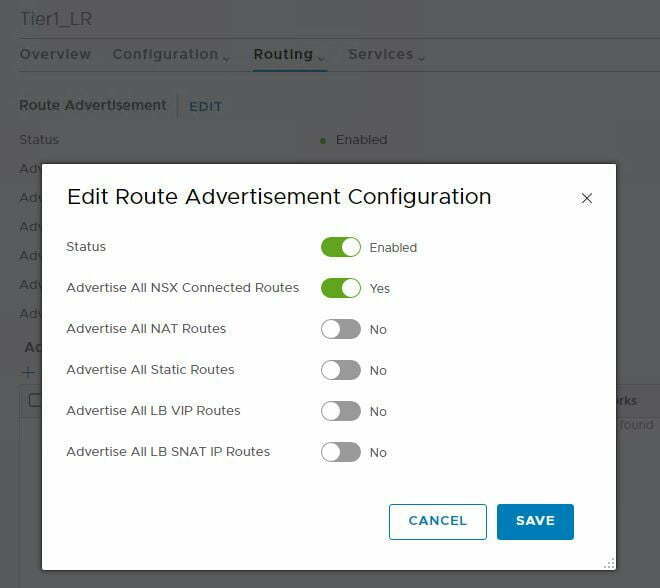
Diagram 3: Advertise connected routes on T1
So if it’s static route what about the connection between the T0 and T1 routers, i.e. the transit link, what does NSX-T use as the next hop for the static route. NSX-T auto-plumbs this element by default using a network from the 100.64.0.0/10 network. So we don’t have to worry about this. It’s all auto-magical. Now once this is all set up and you look at the route table on the Tier-0 router you’ll see NSX Static routes for the connected interfaces on the Tier-1 router. So there you go, east/west routing taken care of without the need for control-VM. Let’s demonstrate how this looks in our environment.
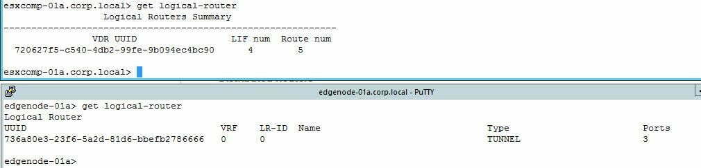
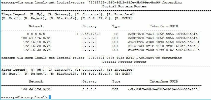
- In my environment, I have a single Tier-1 router defined, which I’ve attached my standard web/app/db logical switches to.
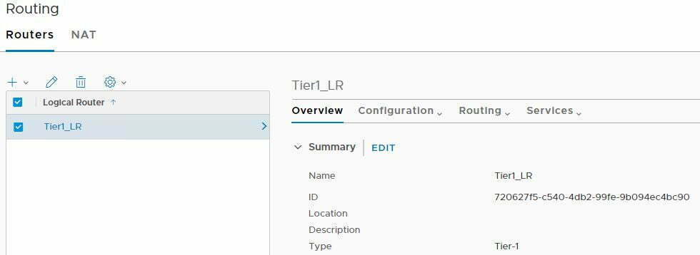
- Note the ID above 7206…. is shown on esxcomp-01a, but it not seen on edgenode-01a. This confirms I have a Tier-1 LR, but with no stateful services, and as the Tier-1 does not have uplink ports as well then there is no requirement for an SR
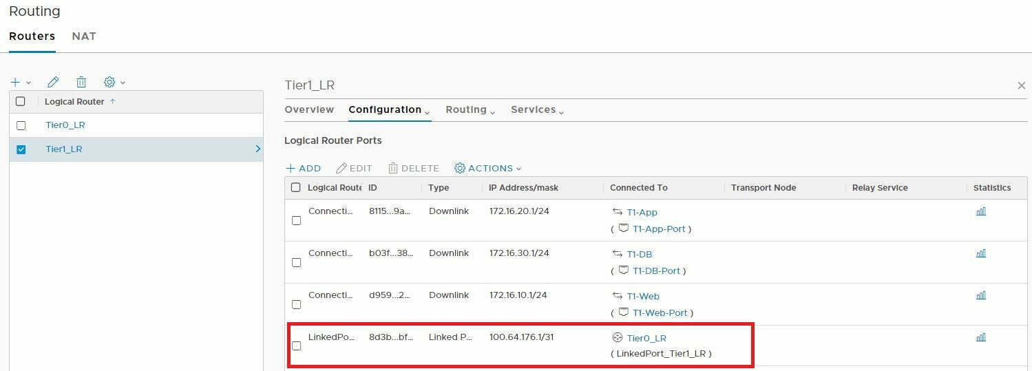
- Next I set up my Tier-0, but I won’t configure any uplinks, but I will attach Tier-1 to it. Notice that the auto-plumbing has already happened.
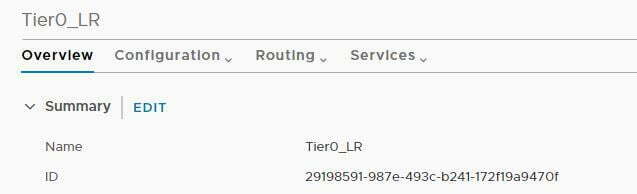
- To confirm let’s validate the ID of T0
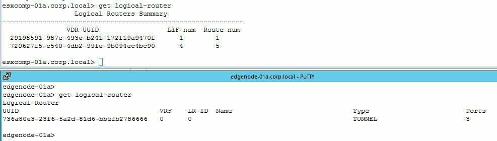
- Now let’s jump onto esxcomp-01a and the edge node, as you can see T0 existing on esxcomp-01a from the perspective of a DR, but as there’s still no uplink or stateful services, there’s no need for it to exist on the edge node
- So now let’s quickly look at routing tables of T1 and T0. As we have not advertised the connected routes on T1 yet they are not visible on T0, but we do see the default route pointing to the T0 and we see the auto-plumbed connected network of 100.64.x.x
- Now I’ll advertise the connected routes on T1 and they should appear on T0
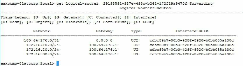
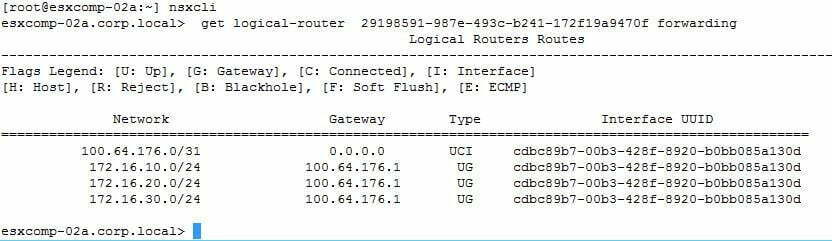
- So that concludes the connected routes being visible on esxcomp-01a at both the T1 and T0 levels. To verify I also went on to esxcomp-02a and validating that the DR instance for T0 existing and the forwarding table matched of esxcomp-01a
In the second part of this article I shall discuss north/south routing and stateful services with the service router.
I hope this helps, as always if you spot any errors please comment below, and I hope this helps in your NSX-T journey.
Thanks


Bal has a proven record of delivering on enterprise network designs, leading data center and site migrations as a result of business mergers and acquisitions, and vendor migrations e.g. Cisco to Checkpoint/Juniper. As part of this he worked across several business sectors: Utilities, Banking, Retail and Government, and can base designs around sector specific standards e.g. PCI-DSS, DSD and ISM. He is proficient in several technology areas including Cisco, Juniper, F5, VMware, Citrix and Microsoft. These skills are supported by non-technical certifications: Prince2 Project Management Practitioner, ITILv3, TOGAF 9.1 Certified and Open Group Certified IT Architect – Open CA.
In addition to supporting the Livefire Team, Bal leads several innovation efforts within the VMware WRACE organization, including projects investigating the use of Virtual Reality/Augmented Reality, AI/ML and Interactive 360, to support customer and partner enablement.
Certifications:
BSc (Hons) Computer Science
CCNP/CCDP
VCDX-NV #269
Open Group Certificated Architect
Member of the Associated of Enterprise Architects
Great walk-through and explanation. Thanks for taking the time to do these. Very helpful.
Thanks for detailed explanation on T1 and T0 components placement specific to DLR and SR function. With detailed info and screenshot able to understand the logic behind easily. Thanks !!!